ST-7XME Camera and CFW-8 Filter Wheel Puzzle (8/9
May 2010)
(Or The Evils of Invisible Infrared Emitters.)
Normally I like puzzles. When they occur at 2:00 AM though they
are harder to solve and I don't like them as much.
I spent most of the early evening training the Periodic Error
Correction subsystem of a Meade LX-200 f/6.3 scope. I do this by
setting up a camera to do autoguiding then use the Meade hand
controller to start the training session. I also run at least a
couple of updates. The updates average the information from the
runs so that periodic worm and main RA gear imperfections can be
automatically compensated for after the training is complete. So
that went pretty well and it was only 1:00 AM or so. So I
decided to shoot some object in my super light-polluted back yard. - If
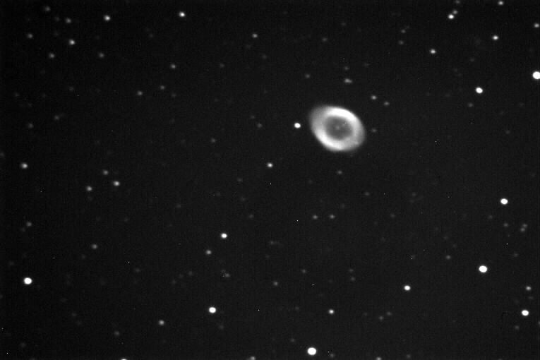
I could find an object bright enough. - Finally settled on M57, the
Ring Nebula. Just to test things out. Was getting images
like this:
Figure 1
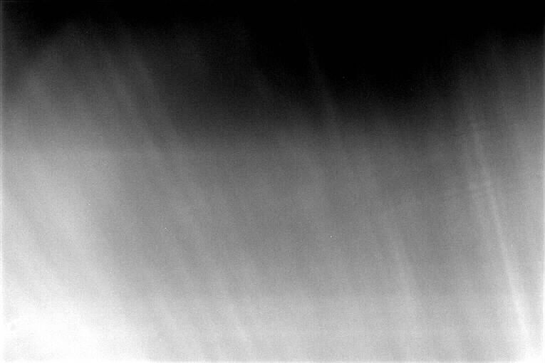
Then suddenly I was getting images like this:
Figure 2
EVERY image looked like Figure 2! If I shot longer image times, I
got the same pattern only brighter! 10 second images reached half
of the maximum pixel brightness (65,536.) Longer exposure were
even worse and easily reached total white-out of the image when all
pixels reached their maximum value. I went outside and looked to
see if the street light was somehow getting into the system.
Nope. I changed the filters from red to green to blue to clear
and shot with each one. They had NO effect on the image. It
always looked like the above image only brighter or dimmer depending on
how long I set the exposure time.
I covered the scope. Got the same results! It was like a
light was shining inside my camera! I took the camera out and set
it down and looked into it while I did an exposure. I could see
no light.
So I thought maybe I had blown the imaging chip somehow. There
was some obscure warning about not allowing it to heat up too quickly
after being cooled (Thermoelectric cooling is a feature of the ST-7
camera.) I have always felt uncomfortable about it because
neither of the programs I use with the camera (CCDSOFT and MaximDL)
dwell on this issue so I don't know if they are doing anything to do
controlled warming or not or whether it really matters.
I also checked for ice on the sensor. No ice. There is a
brass, unscrewable "dessicant container" on the back of the camera that
you can unscrew and bake at 350 degrees for 4 hours to make sure ice
doesn't form on the imaging sensor. (If you ever do this, don't
bake the O-ring!) I did bake my dessicant container several years
ago. Lasts a long time here in the desert...
Nothing I tried worked. Images always looked like Figure 2.
So I forced myself to go to bed at 3:00 AM hoping for better luck in
the morning. At 6:00 AM, I got up and continued work on the
problem. The CFW-8 filter wheel can be mounted directly to the
ST-7XME camera. That is the way I set mine up years ago.
So, naturally, I brought the camera inside, set it up on my desk and
prepared to start taking things apart to see if I could figure out what
was going on. During this time I was thinking that I would have
to send the stuff to SBIG for repair.
First test I did was to cover the camera completely and take an image
to see if the problem was still there (you never can tell whether the
telescope or USB boxes, etc., might be involved. I wondered if
the USB stream had somehow been corrupted... Have had lots of
problems with USB Hubs. Have been using DevManView along with
Device manager to resolve these problems...) Problem was still
there. Switched the camera from my desktop PC to my laptop
PC. Problem was still there.
I then separated the camera from the CFW-8 filter wheel. Tried
the test again with the imaging chip covered so as not to let in any
stray light..
BINGO! I was getting normal images again! Brightness levels
were where they were supposed to be! So the camera itself and its
sensor were OK! Great!
I then put things back together again and got the bad images
again.
Requested the green filter but did not get it. Filter wheel
continued to show the clear filter. Requested the blue filter but
did not get it. Filter wheel continued to show the clear
filter. MaximDL software did not indicate any problem.
CCDSOFT software did not indicate any problem. Neither would
change the filter when I made the request. Took the CFW-8 cover
plate off again so I could watch the attempts to change the
filter. Took camera outside to the scope because I was unsure
whether the filter-change commands came from the USB line or the
Telescope's CCD port. Plugged in USB, CCD, and the power
cord. With the cover plate off and the filter wheel not
constrained by the cover plate, I noticed that as soon as the camera
was plugged in and self-booted, the filter wheel started rotating since
the little motor was running. Put the cover plate back on but
didn't screw it down. Discovered that the commands to start/stop
the filter wheel motor were coming from the USB line and that the CCD
port was not needed. Discovered that the filter wheel was somehow
getting stuck and not rotating!
Finally I saw that the little rods sticking up on the filter wheel were
hitting and stopping on the screw-in adapter's threads! It had
more threads than the one I had always used before! I had always
before used an adapter that screwed onto the standard Meade adapter,
the one that the eyepiece holder usually screws onto. In this
case though, I was trying to use the TCF-S Temperature compensated
focuser which requires a bigger barrel. The adapter with the
bigger barrel that I used had LONGER THREADS than the one I had been
using. This caused an obstruction that the filter wheel was
getting hung up on.
So why the really bad images? Well I then realized that the
little rods that stick up out of the filter wheel are used to reflect
light and determine which filter is selected. What light?
Why the INFRARED light coming from a little chip in the CFW-8 filter
enclosure! So then I was able to deduce this:
When the ST7-XME/CFW-8 combination is powered up, the infrared
emitter is turned on and the filter wheel begins to rotate.
As the filter wheel turns, the little rods sticking up reflect
that infrared light to an infrared sensor which is looking for light
pulses.
There is one place on the filter wheel that has two rods sticking
up that are close together.
As the filter wheel turns, the system is looking for a double
pulse from the two rods that are close together.
The double pulse from the two close rods indicate where the
number one filter position is located on the wheel.
If the system finds the double pulse, the wheel then rotates to
the selected filter by monitoring the pulses generated by the rods
(Clear, Red, Green, Blue, or whatever) and the motor and the infrared
emitter are then turned off.
If the system gets hung up somehow (the filter wheel cannot turn)
the infrared emitter REMAINS ON and the motor remains on.
The motor simply slips against the rubber around the edge of the
filter wheel (poor man's slip clutch.)
The software packages sort of know that the filter wheel has not
rotated properly but do not clearly inform you of the fact.
The light from the infrared emitter
which is still on finds its way to the camera's imaging sensor and that
is what we are seeing in Figure 2 above!
So after taking the Luminance image, I apparently tried to switch to
taking the Red image. The filter wheel then stuck with the
infrared light on which made every image thereafter look approximately
like Figure 2.
So here are images illustrating this further:
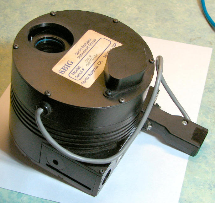
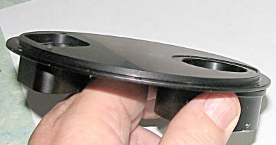
Figure 3 - ST7-XME (bottom) with CFW-8 attached. Top plate is the
cover plate for the CFW-. The hole shows where the adapter needs
to be screwed in. You can also see one of the rods sticking up
from the filter wheel and you can see one of the filters at the bottom
of the hole. (It is the clear filter in this case not that that
is relevant...)
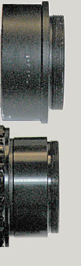
Figure 4 - Items that can screw into the hole above. The new one
I was using is at the top. The old one I had been using is at the
bottom . Note that the top one has threads that will stick out
farther when screwed into the CFW-8 cover plate.
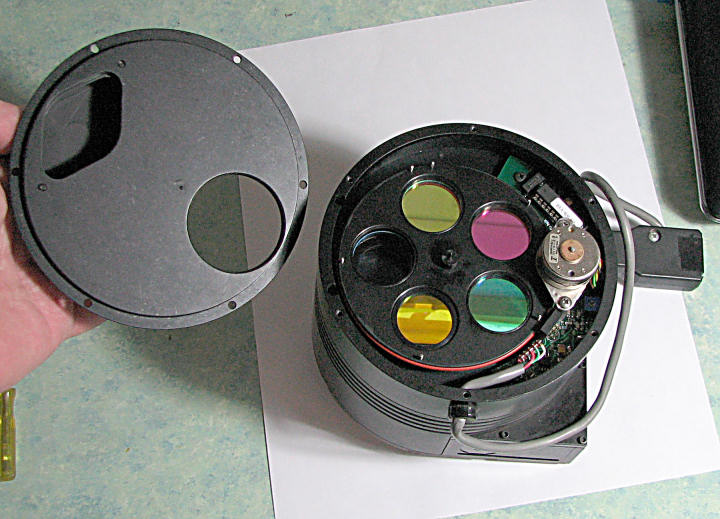
Holding the removed CFW-8 cover plate and showing the filter wheel, the
motor and the infrared emitter.
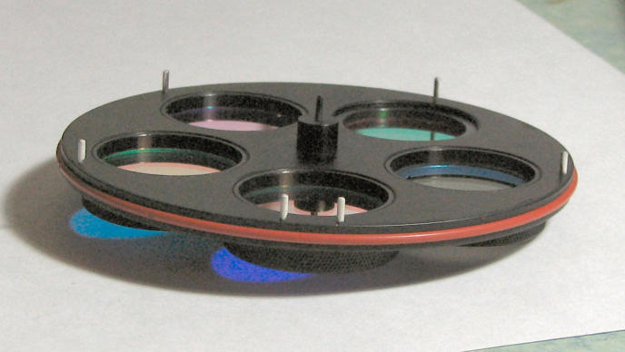
Figure 5 - Filter wheel. Note the little rods sticking up.
These were what were hanging things up when they touched the screw-in
adapter.
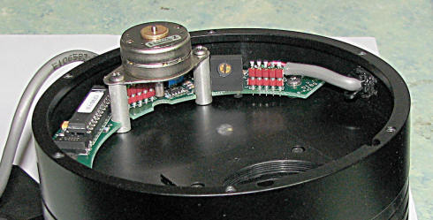
Figure 6. CFW-8 with filter wheel removed. This shows the
motor and, just to the right, the black square with the copper colored
circular region that is the infrared emitter/detector.
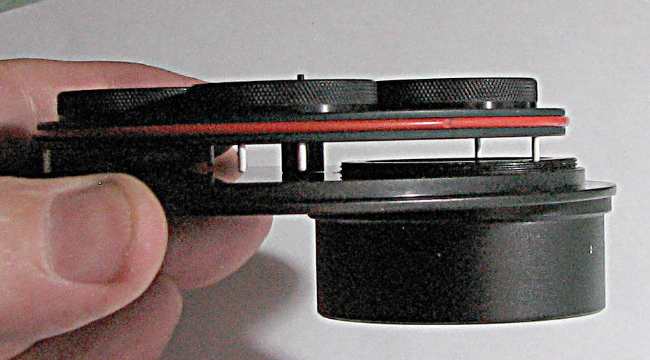
Figure 7 - The filter wheel, cover plate and the screw-in adapter that
was interfering with filter wheel rotation.
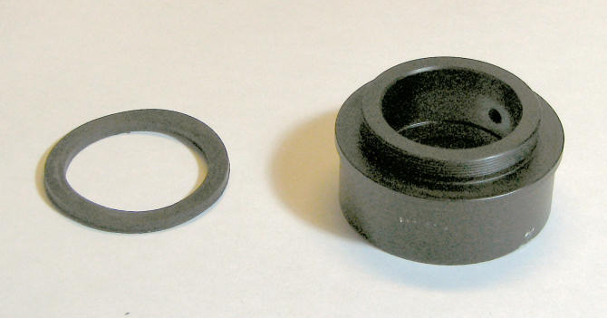
Figure 8 - The solution. Spacer washer to keep the threads from
penetrating so deeply.
Figure 10 - Spacer washer in place.
Figure 11 - CFW-8 cover plate with adapter/washer fully screwed
in. It no longer obstructs motion of the filter wheel...